60Si2Cr Painted D Rail Clip: Material, Hardness and Field Performance
Oct 15, 2025
What a D Rail Clip Does
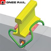
A D rail clip is a bar-formed spring clip, bent into a D or similar open shape, that is driven or bolted into position so that its toe bears on the rail foot and its back locates in an anchor or a shoulder. The clip stores elastic energy and returns it as a downward toe load, holding the rail against the pad and resisting rail uplift, longitudinal creep and gauge widening. Compared with a rigid fastening, the elastic clip keeps a useful clamping force over a wide range of rail deflection, which is what allows it to work on a resilient pad under moving loads.
The type is used widely on light and medium-haul networks, in yards, on secondary lines and in some tramway and industrial track, and it has been a common choice on South American networks. Its advantages are a simple shape, a low number of components and a clamping force that can be tuned by the bar diameter and the free height of the formed clip.
The Material: 60Si2Cr Spring Steel
The clip is formed from silicon-chromium spring steel to grade 60Si2Cr under GB/T 1222, a specification for spring steels. The silicon content raises the elastic limit and the resistance to softening at temperature, while the chromium addition improves hardenability so that a section of this thickness can be through-hardened rather than only case-hardened. Typical heat analysis ranges for the grade are given below; the mill certificate should be checked against the specification rather than against a single supplier's practice.
| Element | Typical range for grade 60Si2Cr |
|---|---|
| Carbon | 0.56 to 0.64 % |
| Silicon | 1.40 to 1.80 % |
| Manganese | 0.40 to 0.70 % |
| Chromium | 0.70 to 1.00 % |
| Form | Hot-formed bar, quenched and tempered |
| Hardness after tempering | Approximately 40 to 48 HRC, verified to ASTM E18 |
Spring steel behaves as a spring only when the whole section has been transformed by quenching and then tempered back to the working hardness. A clip that has been formed and only surface hardened will have a soft core, and the first overload will set it permanently, so the free height and hence the clamping force are lost. Hardness is therefore the key acceptance figure, but a correct hardness reading on the surface is not sufficient evidence on its own: a section through a sample is the reliable check.
Forming, Heat Treatment and Clamping Force
The clip is cut from bar, hot or cold formed to shape, then austenitised, quenched and tempered. Tempering temperature is chosen to reach the specified hardness range: too high and the clip yields under the driving load, too low and it becomes notch sensitive at the bend radii. After heat treatment the clip is usually shot peened at the tensile surface, which introduces a compressive residual stress and materially improves fatigue life at the bends, where service failures normally begin.
Clamping force is a function of bar diameter, the free height of the formed clip, the leg length and the material's elastic modulus. Because the toe load falls as the clip is deflected further, the installed position should be such that the required force is developed at the nominal assembled height, with enough remaining travel to cover pad compression and rail deflection. The clamping force of the assembly, and its retention after repeated loading, are verified by the test methods of EN 13146 and the performance requirements of EN 13481 for the relevant track category.
The Painted Coating System
Painting is a corrosion protection measure, not a finish. A rail clip lives in a wet, abrasive and salt-laden environment, and corrosion at the bend radii and at the toe is what shortens its life. The coating system is applied over a blast-cleaned surface, with the cleanliness and roughness grade specified, and it normally consists of a primer and one or two top coats. A total dry film thickness in the range of about 60 to 120 micrometres is typical for this type of component, and the system should be selected on the corrosivity category of the site, following the durability approach of ISO 12944.
Two practical points are worth insisting on. First, no coating is applied to the surfaces that must not be insulated, and no paint is allowed to bridge the toe or the bearing areas, because a thick film there changes the geometry and therefore the clamping force. Second, any damage to the coating in handling should be touched up before installation, since a bare scratch in a wet environment is where corrosion will start.
Corrosion performance is verified by salt-spray exposure to ASTM B117 on coated samples, together with an adhesion or bend test to confirm that the coating survives the forming and driving operations without flaking. Impact resistance matters: a coating that is brittle will chip at the toe during driving, leaving a bare area at the most highly stressed point of the component.
Installation and In-Service Inspection
Installation should follow the fastening system procedure: the pad is placed on the sleeper or slab seat, the insulating components are positioned, and the clip is driven or bolted so that the toe bears on the rail foot at the designed position. Clips driven to the wrong depth either fail to develop the clamping force or are over-stressed and set. A visual check of toe position relative to the rail foot is the fastest way to confirm correct seating on a production basis.
In service, the inspection points are the toe load, the condition of the pad, corrosion at the bends and in the contact areas, and the presence of any clips that have shed their paint or are visibly set. A clip whose free height has changed no longer presses the rail correctly and should be replaced, because retightening cannot restore the material. Where a large number of clips in one location show setting, the cause is usually track geometry or sleeper condition rather than the clips themselves.
Frequently Asked Questions
Q: What is a D rail clip used for?
A: It presses the rail down onto the sleeper or slab through a resilient pad, holding the rail against uplift, creep and gauge widening while allowing controlled rail movement under load. It is common on light and medium-haul track and in tramway and industrial installations.
Q: Why is 60Si2Cr chosen for rail clips?
A: It is a silicon-chromium spring steel to GB/T 1222 with a high elastic limit and good hardenability at the bar section used for clips, so the whole section can be quenched and tempered to give a stable clamping force instead of a soft core under a hard skin.
Q: What hardness should the finished clip have?
A: Approximately 40 to 48 HRC after quenching and tempering is the usual working range, verified by the Rockwell method of ASTM E18. The figure must be confirmed on a section as well as on the surface.
Q: Does painting affect the clamping force?
A: It can, if paint is allowed to build up on the toe or the bearing surfaces, because the film changes the effective geometry. Coating thickness on functional surfaces should be controlled and the assembly checked after coating.
Q: How is the coating performance verified?
A: By salt-spray exposure to ASTM B117 on coated samples, plus a bend or impact test to show that the film does not flake at the bends during forming and driving. The system is normally selected for the site corrosivity category under ISO 12944.
Q: Can a clip that has lost its clamping force be re-used?
A: No. If the free height has changed, the material has been set and the clip cannot develop the design toe load again. It should be replaced, and the cause of the setting investigated in the track rather than in the clip.